The Cloud Isn’t Magic, It’s a Metaphor: From VMs to Kubernetes on OCI
☁️ Pre-Flight Checklist
This is a connecting flight. Before we taxi down the runway, here’s your flight plan. Keep this handy to navigate your flight path. Welcome aboard the cloud! ☁️
🌥️ Takeoff
- If Dreams Live in the Clouds, the Cloud Makes Them Real
- Level 1: Virtualizing the Computer (The VM)
⛅️ Cruising Altitude
- Level 2: Virtualizing the Operating System (The Container)
- Level 3: Virtualizing the Data Center (The Orchestrator)
- Level 4: Virtualizing the Network (The Roads and Address Books)
- Level 5: Virtualizing the Traffic Flow (The Load Balancer)
- Level 6: Virtualizing Storage (The Foundations and Archives)
🌤️ Landing & Taxi
- Putting It All Together: An OCI Example Architecture
- Conclusion: The Cloud is Your Construction Kit
Enjoy your flight! ☁️
If Dreams Live in the Clouds, the Cloud Makes Them Real
In the first part of this series, we journeyed from the concrete foundation of the data center to the physical servers that form the body of the cloud. We peeled back the layers of power, cooling, and security to reveal the tangible reality behind our virtual worlds.
Now that we understand the physical host, let’s climb up the next rungs of the abstraction ladder. We’ll explore how that physical machine is carved up into the virtual building blocks we use every day. Our journey continues from the virtual machine to the virtualized world of containers, Kubernetes, and the entire cloud ecosystem that lets us turn our ideas into reality.
Level 1: Virtualizing the Computer (The VM)
Before the cloud, you had a physical server. A real, heavy, noisy box in a cold room. The most basic concept in the cloud is virtualizing this box.
- The Concept: A Virtual Machine (VM), which OCI calls a Compute Instance.
- The Analogy: You’re renting a plot of land in a massive, secure technology park (an OCI data center). On this land, you build a complete, self-contained house. This house has its own foundation, walls, plumbing, and electrical system.
- The Reality: A VM is a complete computer emulated in software. It has its own virtual CPU, RAM, storage, and a full operating system (like Linux or Windows) that you choose. It runs on a tiny slice of a very powerful physical server, but to you and your application, it looks and feels like its own dedicated machine.
Level 2: Virtualizing the Operating System (The Container)
Building a whole house for every single application is inefficient. What if you just need a small, standardized apartment for your code to live in?
- The Concept: A Container, most famously implemented with Docker.
- The Analogy: Instead of building a house, you rent a pre-fabricated, standardized apartment inside a larger building (your VM). These apartments are much faster to set up, more efficient, and all look the same on the inside, making them easy to manage.
- The Reality: A container packages your application and all its specific dependencies (code, libraries, runtime) into a single, isolated unit. Crucially, all containers running on a VM share that VM’s operating system kernel. They don’t need a full guest OS, which makes them incredibly lightweight, fast to start, and portable.
Level 3: Virtualizing the Data Center (The Orchestrator)
Okay, you have a city full of apartment buildings. Who manages it all? Who decides where new residents go, handles maintenance, and manages the city’s growth?
- The Concept: A Container Orchestrator, with Kubernetes being the undisputed king. OCI provides this as a managed service called Oracle Kubernetes Engine (OKE).
- The Analogy: Kubernetes is the City Planner or Property Management company for your entire application.
- The Reality: When you have hundreds of containers, you can’t manage them by hand. Kubernetes automates the lifecycle of your containers: scheduling, self-healing, scaling, and networking. Docker builds the apartments; Kubernetes manages the city.
Level 4: Virtualizing the Network (The Roads and Address Books)
Your city needs a private, secure road system and a way for people to find it.
- The Concept: A Virtual Cloud Network (VCN) and DNS.
- The Analogy: The VCN is your city’s entire private road system, complete with neighborhoods (subnets). DNS is the city’s official address book, directing visitors to the right location.
- The Reality: An OCI VCN is your own isolated network inside the cloud where you define your own IP addresses and routing rules. Within it, you create subnets—public ones for resources that need to face the internet, and private ones for secured backend systems. OCI DNS translates your human-readable domain name (e.g.,
your-app.com) into the IP address of your Load Balancer, acting as the entry point for all your users.
Level 5: Virtualizing the Traffic Flow (The Load Balancer)
Your city is popular and the main entrance is getting busy. You need a way to manage the incoming traffic smoothly.
- The Concept: An OCI Load Balancer.
- The Analogy: The Load Balancer is a team of highly efficient traffic cops at the city’s main entrance. They greet every visitor and direct them to the least busy street, ensuring no single road gets jammed.
- The Reality: A Load Balancer receives all incoming application traffic and distributes it across multiple identical containers or VMs. This improves reliability (if one container fails, traffic is sent to others) and scalability (you can add more containers to handle more traffic).
Level 6: Virtualizing Storage (The Foundations and Archives)
Every city needs places to store things, from the foundational materials for buildings to vast public archives.
- The Concept: Block Storage, File Storage, and Object Storage.
- The Analogy: Block Storage is the high-grade concrete foundation for a specific building. File Storage is a shared community bulletin board that everyone can access. Object Storage is a massive, climate-controlled archive for storing anything and everything forever.
- The Reality:
- OCI Block Volumes: A virtual hard drive (SSD) attached to a single VM. It’s fast and used for the OS and high-performance databases.
- OCI File Storage: A network file share that multiple VMs can connect to simultaneously. Perfect for shared content and collaborative applications.
- OCI Object Storage: A limitless storage service for unstructured files (objects) like images, videos, and backups. It’s incredibly durable and cost-effective.
Putting It All Together: An OCI Example Architecture
Let’s see how these levels build a real application. Imagine you have a mobile app on the App Store, and you’re hosting the backend on OCI. A user taps a button.
-
The Address Book (DNS): The user’s phone first asks OCI DNS for the address of
api.your-app.com. DNS replies with the IP address of your Load Balancer. -
The Traffic Cop (Load Balancer): The request arrives at the OCI Load Balancer, which sits in a public subnet of your VCN. It checks the traffic and forwards the request to a healthy application container.
-
The Application (Kubernetes): The request reaches an application container managed by your Oracle Kubernetes Engine (OKE) cluster. The container, running your code, now needs to fetch and store data.
-
The Brains (Databases): This is where the app interacts with its databases, which are safely hidden in a private subnet.
- To verify the user’s identity, the app queries a PostgreSQL database. We chose Postgres because it’s a relational database, perfect for the structured, predictable format of user profiles and login information. OCI offers this as a Managed Database Service, so our team doesn’t have to worry about patching or backups.
- To fetch the product catalog, the app queries a MongoDB database. We chose Mongo because its flexible, document-based structure is ideal for product listings, which might have different attributes and complex data. We run this on a dedicated Compute Instance with a high-performance Block Volume attached.
-
The Archive (Object Storage): The user wants to upload a new profile picture. Your application takes the file and writes it to OCI Object Storage, receiving a unique URL for the photo in return. This URL is then saved in the user’s profile in the PostgreSQL database.
-
The Journey Home: The application assembles the final response and sends it back through the Load Balancer to the user’s phone.
Visualizing the Architecture
Architects and developers use diagrams to map out these connections visually. Let’s represent our application flow using the C4 model, a popular approach for structured architectural diagrams. This specific diagram is at the Container level, showing how major components interact.
@startuml
!includeurl https://raw.githubusercontent.com/plantuml-stdlib/C4-PlantUML/master/C4_Component.puml


Person(user, "User", "Accesses the system")

System_Boundary(oci, "Oracle Cloud Infrastructure (OCI)") {

    Container_Boundary(vcn, "VCN (10.0.0.0/16)") {
        Container(igw, "Internet Gateway", "Gateway", "Handles ingress/egress traffic")

        Container_Boundary(pub, "Public Subnet (10.0.1.0/24)") {
            Container(lb, "Load Balancer", "OCI LB", "Distributes traffic")
            Container(oke, "OKE Cluster", "Kubernetes", "Hosts application containers")
        }

        Container_Boundary(priv, "Private Subnet (10.0.2.0/24)") {
            Container(nat, "NAT Gateway", "Gateway", "Outbound internet for private subnet")
            ContainerDb(psql, "PostgreSQL DB", "Database", "Stores user profile data")
            ContainerDb(mongo, "MongoDB", "Database", "Stores product catalog")
        }
    }

    Container(storage, "Object Storage", "Storage", "Stores user photos")
}

Rel(user, igw, "Public Traffic")
Rel(igw, lb, "Public IP: 130.x.x.x")
Rel(lb, oke, "Routes requests")
Rel(oke, psql, "Fetch user profile")
Rel(oke, mongo, "Fetch product catalog")
Rel(oke, storage, "Stores user photo")
Rel(oke, nat, "Outbound Internet")
Rel(nat, igw, "Internet Access")

@enduml
How to Read the C4 Diagram
This C4 Container diagram provides a clear, structured view of our cloud architecture. The C4 model helps you describe, explain, and document software architecture using a set of hierarchical diagrams:
- Context (Level 1): Shows how your system fits into the user’s world and interacts with other systems.
- Container (Level 2): Decomposes the system into high-level building blocks (e.g., web application, database, mobile app) and their interactions. This is the level of our current diagram.
- Component (Level 3): Decomposes a container into its constituent components (e.g., controllers, services, repositories).
-
Code (Level 4): Provides the lowest level of detail, showing the implementation of individual components (e.g., classes, interfaces).
-
C4 Elements:
-
Person: Represents a human user. -
System_Boundary: A large box representing a major system (like OCI). -
Container_Boundary: A box representing a logical grouping of containers (like a VCN or a Subnet). -
Container: A deployable unit (like a Load Balancer, OKE Cluster, or Gateway). -
ContainerDb: A container specifically for a database. -
Rel: Represents a relationship or flow between elements.
-
-
Boundaries & IP Addresses: The boxes show the layers of our architecture, now with example IP address ranges (CIDR blocks) for the VCN and its subnets. This helps visualize the network segmentation.
-
Internet Gateway (IGW): This is the virtual router that connects your VCN to the public internet. All traffic from the internet to your public resources (like the Load Balancer) and vice-versa passes through here.
-
Public vs. Private Subnets: Notice how the arrows from the Internet only lead to the Public Subnet. This is our application’s front door. The databases are in the Private Subnet, with no direct inbound arrows from the outside world. This is a fundamental cloud security practice.
-
NAT Gateway: For resources in the Private Subnet (like your databases or even application containers that need to download updates), the NAT Gateway allows them to initiate outbound connections to the internet without exposing them to inbound connections. It acts as a secure proxy for outbound traffic.
-
The Flow: The
Relarrows trace the journey of a user’s request:-
UserinitiatesPublic Trafficto theInternet Gateway. -
Internet Gatewayroutes traffic to theLoad Balancer(which has a public IP). -
Load BalancerRoutes requeststo theOKE Cluster(your application). -
OKE ClusterFetches user profilefromPostgreSQL DBandFetches product catalogfromMongoDB. -
OKE ClusterStores user photoinObject Storage. - For outbound internet access from private resources,
OKE Clusteruses theNAT Gateway, which then accesses theInternetvia theInternet Gateway.
-
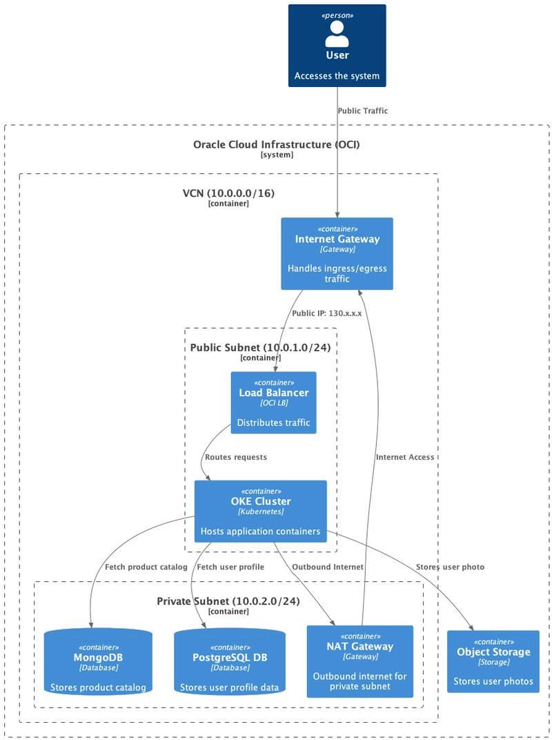
The arrows trace the journey of a user’s request. It comes from the user, passes through the Internet Gateway, hits the Load Balancer (which has a public IP), goes to your application in Kubernetes, and then the application communicates with the necessary databases and storage services. Outbound traffic from private resources uses the NAT Gateway.
Designing a cloud architecture is all about choosing the right virtualized services for the job and connecting them in a secure, scalable, and efficient way to bring your application to life.
Conclusion: The Cloud is Your Construction Kit
The cloud isn’t a mysterious, unknowable entity. It’s a powerful set of virtual, standardized building blocks. By understanding that every service is simply an abstraction of a real-world piece of hardware, you can demystify the jargon and see the cloud for what it truly is: a construction kit for turning your ideas into reality.
So next time you think of a dream application, don’t just let it float away in the clouds. Grab your virtual tools and start building.
Happy Building! ☁️
Cover Photo by BoliviaInteligente on Unsplash